|
|
Computer Control Devices and CircuitryMaster Clock Transmit DeviceThe Master Clock Transmit circuit requirement is very simple - monitor when the contacts open, and upon opening transmit a message to the Slave Clock telling it to advance. This is accomplished using the Raspberry Pi's GPIO (General Purpose Input Output) interface. GPIOs can be programmed for input, in which case they can detect whether a 3.3 V DC voltage is applied (considered the High state), no voltage applied (considered the Low state) or a transition from one state to the other has occurred. The GPIO is a physical pin on the interface connector, and the complete Pi GPIO interface includes pins for 3.3 V DC and Ground and some additional pins for other specific protocols. The left-hand side of the circuit below shows the connection from the contacts to the GPIO assigned for detection of the contact opening (GPIO DET) and to Ground. While there are additional components in the schematic, the contacts and the GPIO/Ground are all that is needed for the Master Clock. The right-hand side is optional. It is designed to provide status information and will be discussed next. For now, the GPIO DET is initialized to be in the High state on start up and when the contacts are open. When the contacts close, the GPIO DET is connected to Ground and the system recognizes this configuration as the Low state. Using this information, the program can detect when the contacts open (using either the Low state or the transition from High to Low, depending on the programmer's preference) and send the message to advance to the Slave Clock.
As mentioned, the right-hand side of the circuit is used for indicating the status. The red GPIO CLOSED and green GPIO ACK LEDs are connected through a 220 Ohm resister to 3.3 V DC and their respective GPIO pins. Both pins are initialized to the High state. In this condition, no current flows and the LEDs are off. When the contacts are closed (which occurs 2 seconds prior to the minute for about 2 seconds) the GPIO CLOSED pin is set to the Low state and current flows lighting the GPIO CLOSED LED. When the contacts open, the LED is turned off. The GPIO ACK LED is used to confirm that the Slave Clock received the message to advance. After the Slave Clock advances its minute hand, it responds to the Master Clock with an Acknowledge message. On receiving this acknowledgment, the Master clock will turn on the GPIO ACK LED by setting its state to Low. When the Master Clock's contacts close, the GPIO ACK LED will be turned off by setting its state to High. If the Master Clock receives more than one acknowledgment before the contacts close again, the GPIO ACK LED will be set to blink until the contacts close and an event will be logged. If the Master Clock receives more than one acknowledgment during the two second period while the contacts are closed, an event will be logged. If the Master Clock does not receive an acknowledgment before the contacts open, an event will be logged. Master Clock Transmit Circuit Names to GPIO Pin Number Mapping
Master Clock Transmit Device
Master Clock Transmit Circuit Parts List
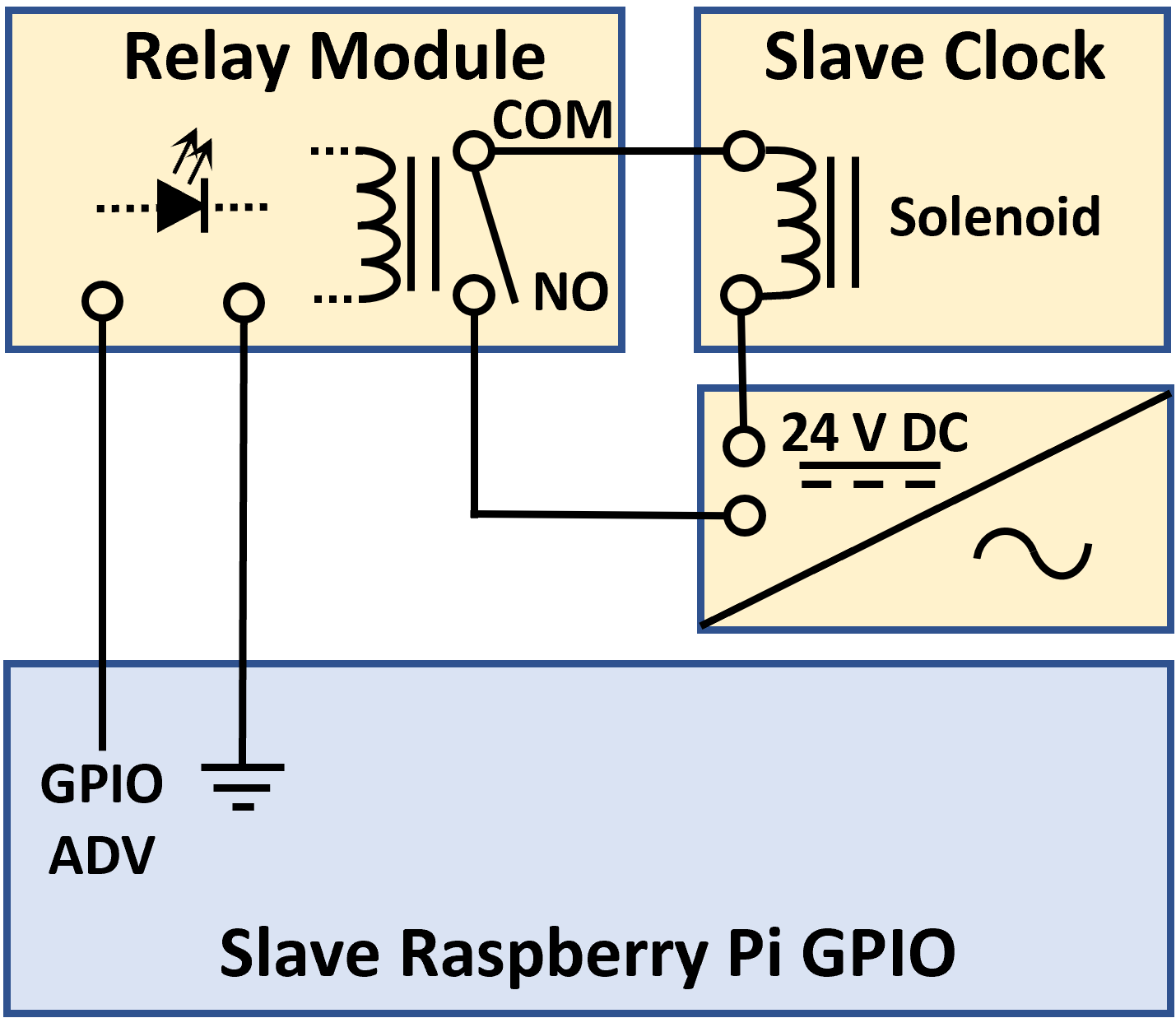
Programming for Master Clock transmit circuit to detect the contact opening and closing and activate the status LEDs is discussed on the next page. Slave Clock Receive DeviceThe Slave Clock circuit is a little more complex, but many of the components are available in ready-to-use packages like the opto-isolated relay module. Years ago, this module would have had to be built from individual resistors and other base level components, but now these modules are an easy to find commodity. Once again, GPIO pins are used as the primary interface from the Pi computer to the hardware. In this case GPIO ADV is used to drive the relay module after the message to advance has been received. It is initialized to Low and no current flows to the relay. After the message is receive, the program sets GPIO to High for 2 seconds and the relay is engaged during that period. When the GPIO ADV returns to to Low, the relay is disengaged and the minute hand advances. The relay module is connected to the solenoid and 24 V DC power supply using the NO (Normally Open) and COM contacts on the relay module. The program then sends an Acknowledgment message the Master Clock to confirm the operation has been completed. The additional complexity of the Slave receive circuit, besides driving the relay, includes a pair of button switches and LEDs. The switches (GPIO ADV Button and GPIO HOLD Button) are used to set the clock by either advancing the minute hand once per second, or holding it up so advance messages from the master clock are ignored. The buttons can be latched so they do not need to be held manually. The LEDs GPIO ADV LED and GPIO HOLD LED) are used to indicate when the advance or hold activity is in progress. The receive circuit is shown below. The relay module includes an on-board LED, which lights when the relay is engaged, so a separate status indicator is not required.
Slave Clock Receive Circuit Names to GPIO Pin Number Mapping
Slave Clock Receive Device
Slave Clock Receive Circuit Parts List
Programming for Slave Clock receive circuit to receive the message to advance, engage its solenoid and acknowledge this activity is discussed on the next page. Time Delay AdjustmentThe ITR service manual recommends that the contacts levers be adjusted to allow for a two second contact closer. The reopening of the contacts should occur exactly at the top of the minute. This is designed to ensure that all Slave Clocks have fully activated their solenoids and the hook is properly engaged to advance the ratchet wheel and minute hand when the solenoid disengages. Each Slave Clock should then advance at the exact same time the Master Clock reaches the top of the minute. To understand the reason for the adjustment when using the Internet, it helps to realize that the dropping of a lever off of a cam is easier, more reliable and consistent that determining when the lever is raised to a specific point. So, the detection of the open is used as the trigger for both the hardwired and Internet versions. The Slave clocks still need their two second activation to ensure the proper mechanical advance sequence. In order to synchronize the minute hand advancing on both clocks using the Internet version, the trigger must be sent and received two seconds sooner. So, the Master Clock cam is adjusted accordingly. With that adjustment, the Master Clock contacts close at 56 seconds and open at 58. The message to advance is sent and received at 58 (not counting any lag time). The Master Clock cam is adjusted by rotating it slightly counterclockwise on its shaft to open and close the contacts at 56 and 58 seconds instead of 58 and 00. The Slave Clock then activates its solenoid at 58 seconds for two seconds and disengages the solenoid at the top of the minute as originally designed. |
Clock Repair & Restoration