|
|
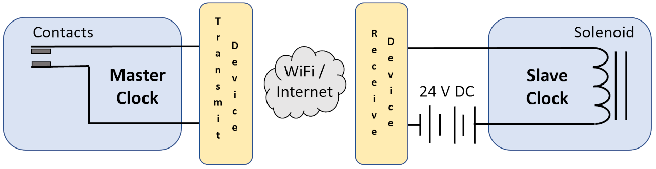
Computer Controlled Time Synchronization Using WiFiTo eliminate the need for physical wires connected between the clocks, they are replaced with a WiFi transmit device in the Master Clock to detect the closing of the contacts and send a message to a WiFi receive device in the Slave Clock. Upon receiving the message,the receive device enables the solenoid circuit to advance the minute hand. The modernized schematic is shown here.
The primary component in the transmit and receive devices is a Raspberry Pi computer. The Pi in the Master Clock is connected to the contact circuit and programmed to detect the opening and closing of the contacts. When the contacts opening is detected, the transmitting Pi sends a message to the Receiving Pi in the Slave Clock. The receiving Pi's program then activates a relay module to enable the 24 V DC Slave Clock solenoid mechanism. The Raspberry Pi 400 is shown below (front and back). The size is about 11-1/4 inches by 5 inches by 3/4 inch on the back (28.5 cm by 12 cm by 2 cm).
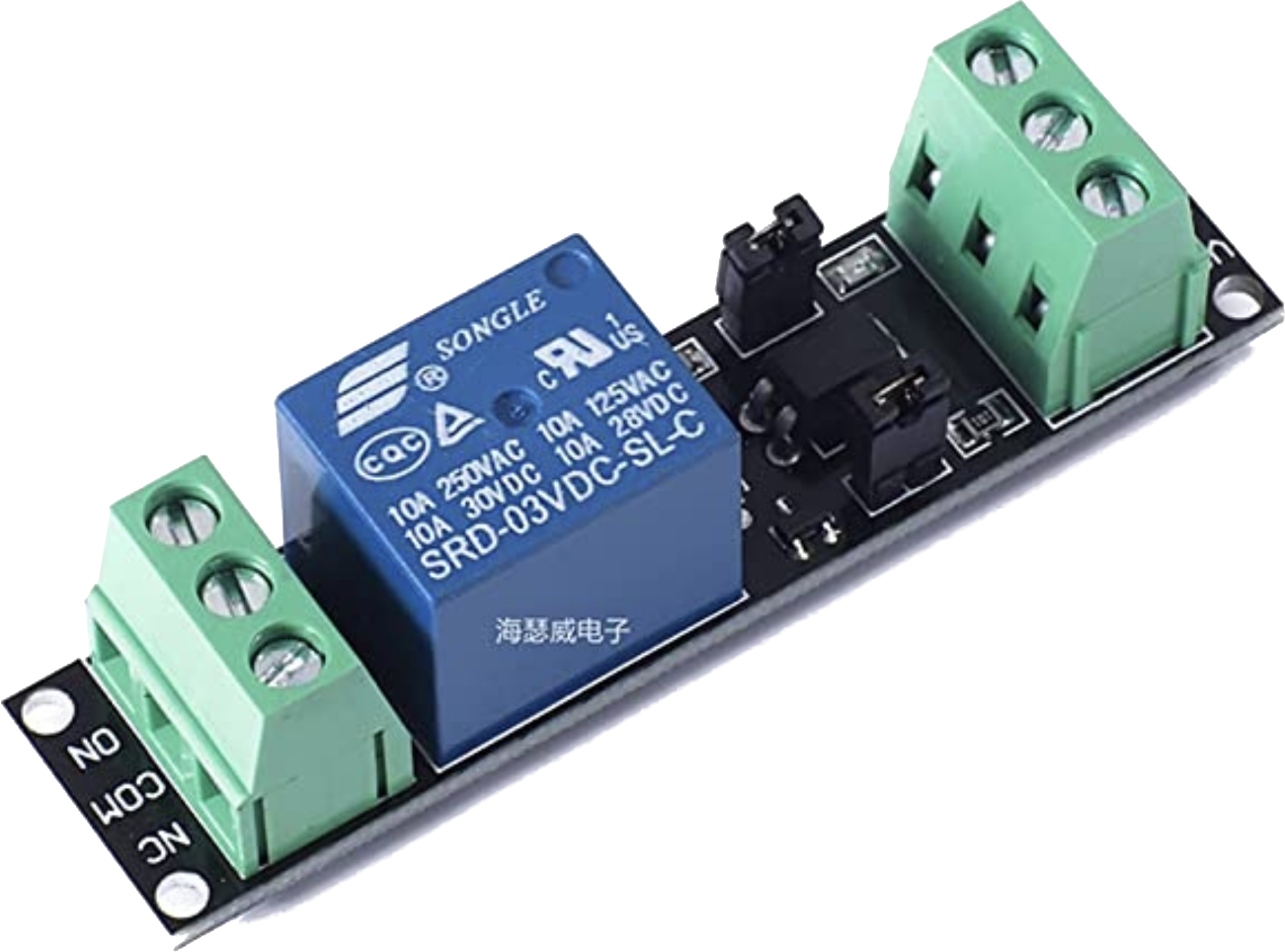
The opto-isolated relay module is shown below (not to scale). The module is about 2-3/4 inches by 5/8 inch by 5/8 inch (7 cm by 1-1/2 cm by 1-1/2 cm)
The remainder of the components required include a 24 V DC power supply for the Slave Clock advance mechanism and a 5V DC power supply for each Raspberry Pi, and miscellaneous wires, connectors and LEDs to serve as status indicators. The transmit and receive devices are described in more detail on the next page. |
Clock Repair & Restoration
Example Custom Design Projects > ITR Modernization > WiFi Synchronization
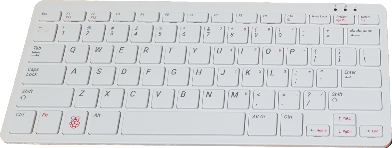 Front
Front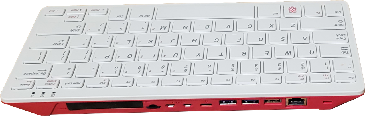 Rear
Rear