|
|
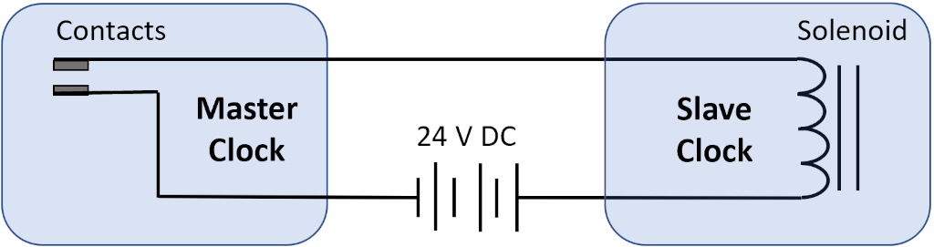
Original Wired Time SynchronizationTo maintain time synchronization, this ITR Master / Slave Clock pair uses an electro-mechanical time advance system. The system consists of a 24 V DC power source with set of contacts on the Master Clock that close for 2 seconds before the minute and reopen precisely at the start of each minute. This circuit is connected to a solenoid in the Slave Clock that drives a ratchet wheel mechanism to advance the minute hand. When the contacts close, the solenoid engages and moves a lever in position to pull the minute hand one minute forward when the contacts reopen and the solenoid disengages. This simple circuit schematic is shown here.
Master Clock Mechanism
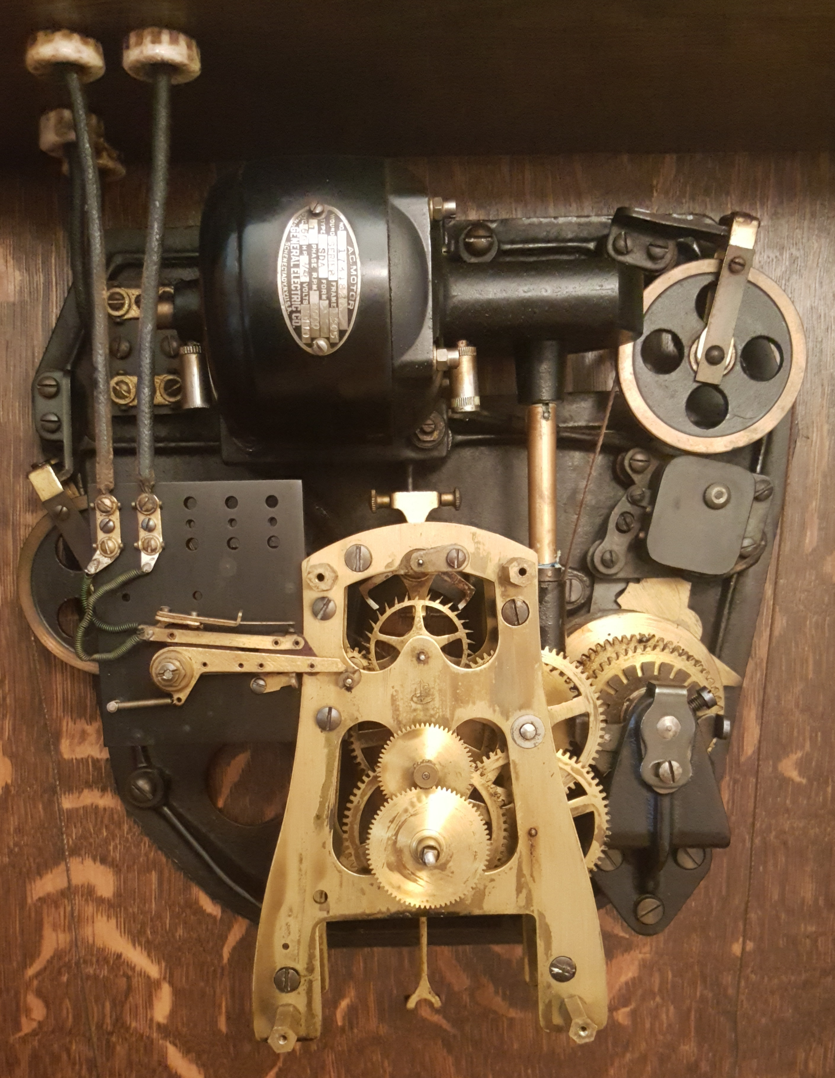
The Master Clock uses a weight driven movement with a deadbeat escapement and a one second pendulum. These features improve the timekeeping accuracy. The movement also includes a electric motor to rewind the weights automatically. The weights motor drive train is started or stopped using its own cam system. The drive train is connected to the clock using a planetary gear system, so the weights continue to drive the clock even when they are being raised. Slave Clock Mechanism
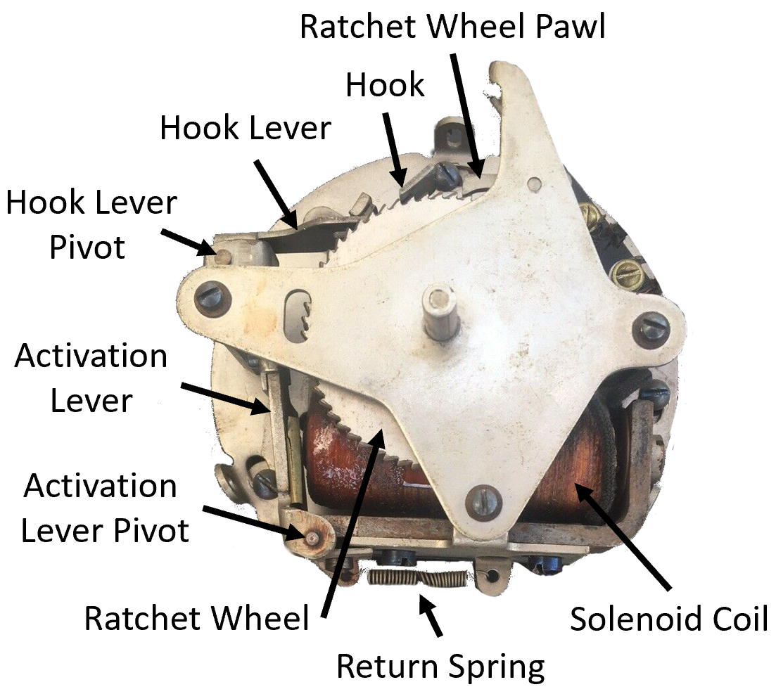
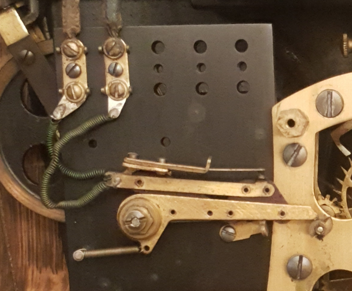
While the Master Clock uses a traditional weight driven clock mechanism, the Slave Clock uses a solenoid to advance a ratchet wheel one minute at a time. When the solenoid is engaged, it pulls the activation lever on the left toward the right. At the top of the activation lever is an arm with a hook that slides over one tooth on the ratchet wheel. The ratchet wheel pawl prevents the ratchet wheel from moving backwards when the hook moves over the next ratchet wheel tooth . When the solenoid circuit opens, the spring at the bottom returns the activation lever to its original position and the hook pulls the ratchet wheel one tooth forward to advance the minute hand one minute. Note that the image above is from the rear, so from this view the ratchet wheel is rotated counterclockwise. From the front of the clock, that direction is clockwise. ITR Master / Slave EvolutionThis model of these clocks is an early version of these Master / Slave Clocks. This model can only advance the minute hand and there is no way to detect or correct an error. As these clock systems evolved, enhancements were made to ensure that the Slave Clocks could be automatically adjusted if for some reason they got ahead or behind. This automatic self correcting feature required more electric circuits and mechanisms. Further enhancements included the ability to program events, such as to ring bells to mark the start or end of classes or a work shift. Here is a video from another clock collector describing the automatic correction feature in detail. You can see the Master Clock contacts and Slave clock advance mechanism are much more complicated than the older, simpler two wire circuit. Also the Master Clocks in the video are spring driven with an automatic winding circuit driven by a solenoid. Note that the solenoid does not drive the clock as is done in the Slave Clocks. The solenoid winds the Master Clock's mainspring to ensure it does not wind down. |
Clock Repair & Restoration
Example Custom Design Projects > ITR Modernization > Time Synchronization
.jpg)